Whenever you are installing a PSU, you might feel a bit overwhelmed by a bunch of cables emerging out of it. Plus, the design of the connectors look so similar that it’s hard to figure out which one goes where.
It is always crucial to be familiar with the power supply connectors toensure stable and efficient power deliveryto each of the PC components. Although the available connectors vary depending upon your PSU model and manufacturer, there are some common ones you’ll always find.
In this article, I’ll be discussing theATX power connectorthat supplies power to your main board and theCPU power connectorthat gives power to the CPU. Besides, you’ll also learn how thePCIeandSATA connectorspower up your GPU and storage disks respectively. By the end, you’ll also get some insights on aMolex connector, which is, however, quite less used these days.
24 Pin ATX Power Connector
It is the largest connector on a PSU thatsupplies power to the main board, including RAM, chipsets, and onboard storage devices (like aNVMe SSD.)
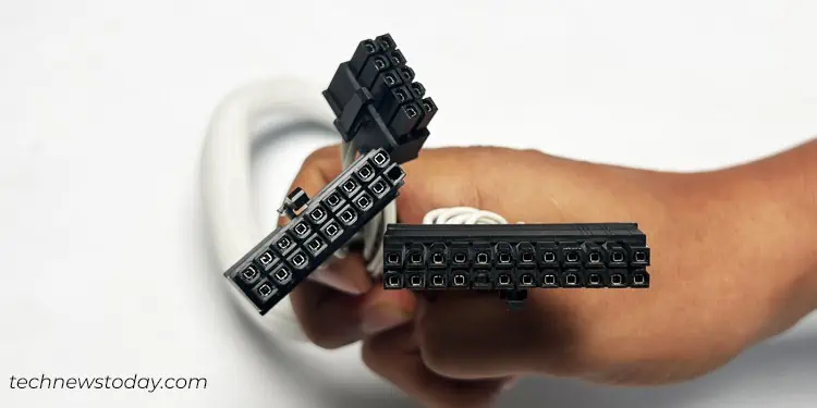
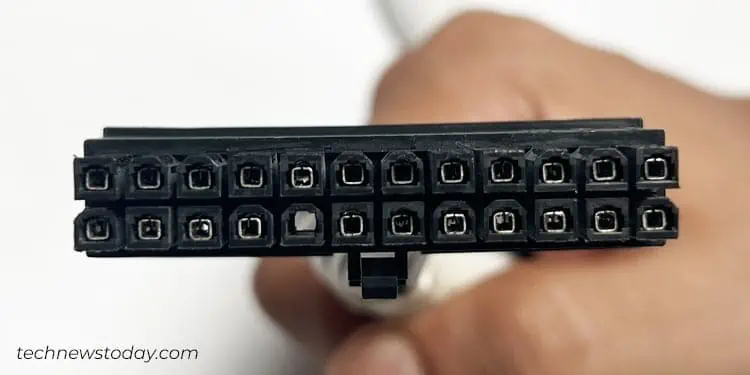
If you observe these connectors closely, you will find that it has24 pins arranged in 2 rows, 12 on each.
For instance, you may see the ATX power connector that came with myCORSAIR RM850XPSU. It can be easily plugged into the motherboard that has a 24-pin ATX header.
However, you may also find some connectors that are divided into two blocks of 20 pins and 4 pins. The(20+4) pin setupwas introduced for enhanced compatibility, allowing you to use the same connector regardless of the pin setup on your main board.
For instance, if you have an older motherboard with a 20-pin ATX header, you can simply attach the 20 pins block and let go of the four pins block.
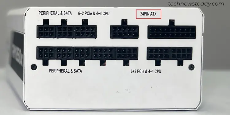
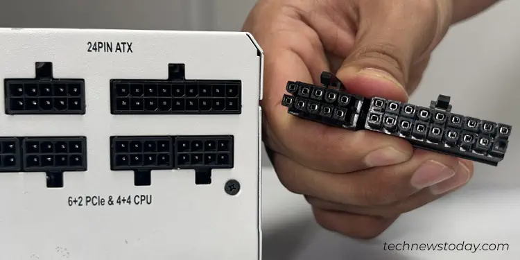
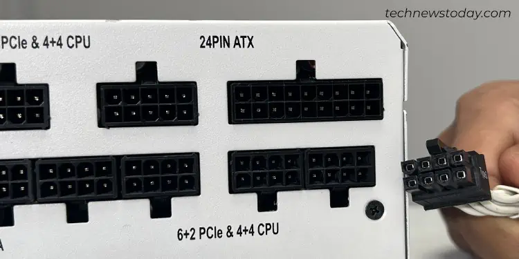
Coming to the PSU side, you will see a “24PIN ATX” label to connect the ATX power connector. However, the ATX port on the PSU may not always have a 24-pin setup.
For instance, myCORSAIR RM850XPSU has a 28-pin configuration, in a set of (18+10.) The additional 4 pins are integrated to sense voltage drop in the component end, if any, and report it back to the PSU.
Now that you know the basics of an ATX power connector, let me show you how to connect it to your main board.
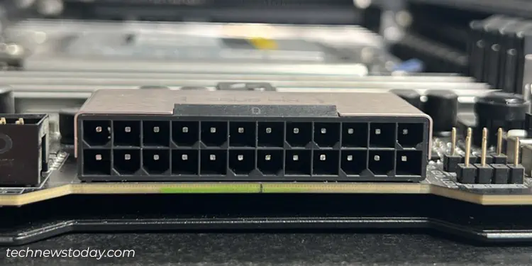
TheATX headeris generally found in the rightmost part of a motherboard, usually with anATXorATX_PWR1label. Below is my ATX header on aGIGABYTE TRX40 AORUS MASTER.
you’re able to simply locate it on your board and plug in the connector. For simplifying the connection process, the connectors are notched and keyed one side, making it almost impossible to insert the cable incorrectly.
12V CPU Power Connector
As you might have guessed, the CPU power connector is the one thatpowers your CPU.
Referring back to the ATX power connector, it does supply some power to the CPU. However, not enough that it can operate correctly. Your system can not boot without the 12V CPU power connector installed.
Therefore, PSU manufacturers provide a dedicated power connector to ensureproper voltage supplyand stability to the CPU.
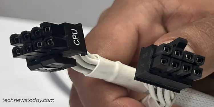
Coming to the pin configuration, the CPU power connector either has a4-pin,8-pin,(8+4) pin,or an(8+8) pinsetup. Among all, the 8-pin setup is widely used these days and considered a standard. The 8-pin setup is detachable into two blocks of (4+4) as you’re able to see in myCORSAIR RM850X PSUconnectors.
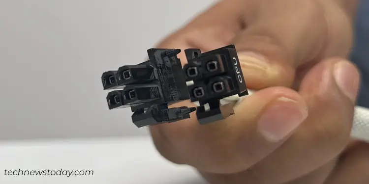
While the 8-pin configuration is backward compatible with the 4-pin ones, the 4-pin ones are not. To be more precise,you can plug the 8-pin connector to the 4-pin header on your motherboard, leaving one-half disconnected but not vice-versa.
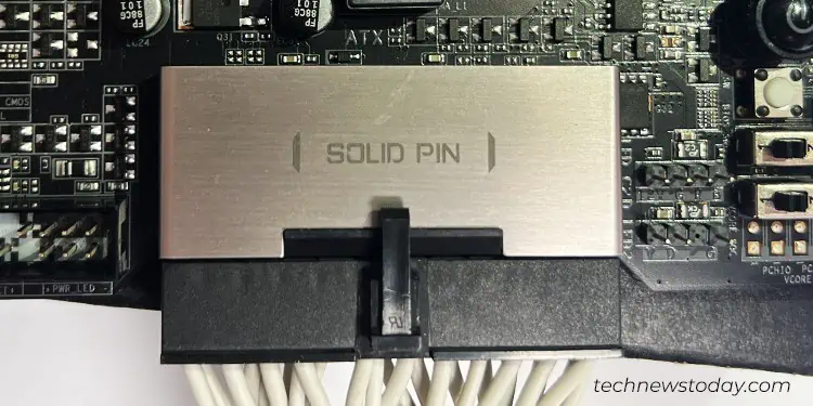
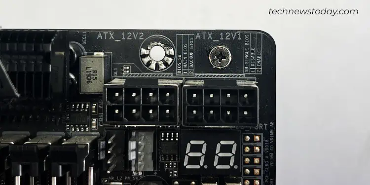
However, no matter the setup, you’re able to simply connect it to theATX_12V headerthat lies near the CPU socket on your motherboard.
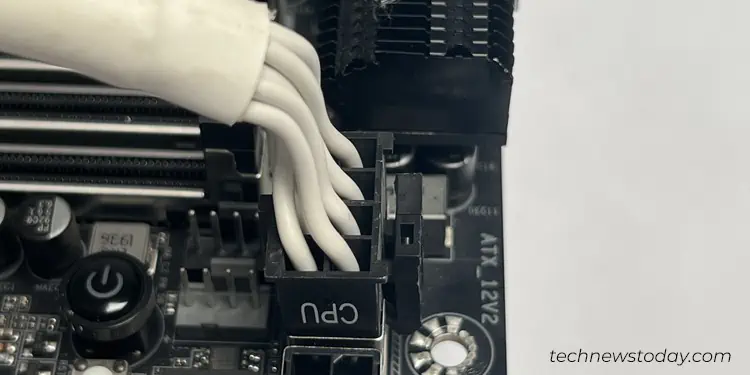
Some high-end boards may even include two ATX_12V headers, like in myGIGABYTE TRX40 AORUS MASTER. Generally, the second one is provided to accommodate a 4-pin or 8-pin auxiliary connector that provides extra power and stabilizes theoverclocked CPU. As such, you need to grab two CPU power connectors and plug them into each header.
Coming to the PSU side, you will find a dedicated port with 8 pins to plug the CPU connector. They are generally labeled as “CPU” to help you connect effortlessly.
PCIe Connector
The next connector in our list is the PCIe connector which is generally used topower up the GPUs.
In general, if you have a low-end GPU rated below 75W, the power delivered from thePCIe x16 slotis sufficient to operate it. To be more precise, you don’t need toconnect your GPU to PSUin such cases. However, if you have a power-hungry GPU, it does require a connection with the PSU.
You often get multiple PCIe connectors with your PSU in adaisy chain fashionmaking it easier to connect more than one PCIe component.
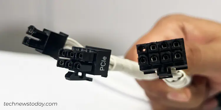
Similar to the standard 12V CPU power connector, the PCIe connector also has an 8-pin configuration. However, unlike the CPU ones, these are divided intotwo detachable blocks of 6-pin and 2-pinsrespectively. There are also other variants like one with the 12 or 16 pins.
While the (6+2) pins PCIe connector is sufficient to supply power to the mid-range GPUs, you will require12 pinsor16 pinsto feed the power-hungry GPUs. For instance, you will find two 8-pin ports (16 in total) on aGeForce GTX 1080 Ti GPU.
Similarly, if you have a high-end GPU that requires a single 16-pin connector, you should opt forPCIe 5 compatible ATX 3.0 PSUslikeMSI MPG A1000G PCIE 5 & ATX 3.0 Gaming Power Supply. Such PSUs have a dedicated 16-pin port (+12VHPWR) to accommodate those connectors and provide up to a whopping 600W.
Additionally, the high-end GPUs are bulkier in size, making it difficult to plug the PCIe connector into it, often when you are using a smaller PC case. In such cases, you may use aPCIe 90 Degree Adapterto get the job done.
Coming to the PSU side, they have the same 8-pin configuration that resembles the CPU ones.
While you may see separate 8-pin ports for CPU and PCIe (VGA) in some PSUs like in myEVGA Supernova 550 G3, some of them may have the same port for both of them.
So, verify youinspect the labeland insert the connectors accordingly. If the labels are not clear, you may refer to the manual of your PSU to identify the respective ports.
SATA Connector
As the name suggests, this connector is used topower SATA interface deviceson your system. It can either be storage media like a hard disk drive and Solid State Drive (SSD,) or other supplementary components like a RGB and fan controller device.
Talking about the pin configuration, it has a single block of15 pinsenclosed in a flatL-shaped housing. The unique shape of the connector helps you connect it to a SATA interface device effortlessly. Below you can see the SATA connector that came with myCORSAIR RM850X PSU.
Coming to the PSU side, the connector has aset of 6 pinsand a corresponding port labeled “PERIF” or “PERIPHERAL& SATA” to connect to. If you are having any problems with the connector, you can also refer to our comprehensive guide on how toconnect the SATA power cable.
Molex Connector
The newer standards like PCIe and SATA have almost replaced the use of Molex connectors these days. However, if you got one, you can use it topower the Molex interface deviceslike a CD/DVD drive, floppy disk drive, or a PATA interface hard drive.
Additionally, you’re able to also pair Molex connectors with theSATA adapters. It can be helpful to power multiple SATA disks if the existing connectors are insufficient.
These connectors generally have a4-pinconfiguration in a single row. But you might also find ones that have 4 pins, two on each row. Some of them even have aBerg connectorat the end to power a few variants of floppy drives.
Coming to the PSU side, these connectors are pretty similar to the SATAs and have aset of 6 pins.
While some PSUs provide a dedicated “PERIF” port for Molex connectors like in myEVGA Supernova 550 G3,some may have the same port forSATAandPERIFlike inCORSAIR RM850X PSU.
You should always read the label on yourmodular or semi-modular PSUand insert the connector accordingly. However, you don’t need to worry much if you have a non-modular PSU.
Further, I also recommend you only use the proprietary connectors (that came bundled with your PSU.)
For instance, you may see above how the pin configuration of a Molex connector differs between myCORSAIR RM850XandEVGA Supernova. The difference in pinouts may even end up damaging your device if you swap the cables.
