If you’re relatively new to electronics and wish to troubleshoot electronic devices on your own, it’s essential to have a proper knowledge of multimeters.
In the earlier days, we were limited to analog devices, which were quite difficult to operate. But now, you can find a variety of digital multimeters that allow you to select a wide range of measurements (manually or automatically). Also, it can display the measured values digitally on a screen, making it easy for even beginners to operate the instrument.
All digital multimeters can measureAC/DC voltages, currents, and resistance. Moreover, some even let you testcontinuity, hFE, capacitance, temperature, square wave, and frequency! In this article, I will guide you through everything that you should know about a digital multimeter and how to measure the different values.
Safety Tips Before Using a Digital Multimeter
If you’ve already purchased a digital multimeter, I highly recommend checking the user manual before operating it. It’s essential to know the basics and the warnings.
First and foremost, note the instrument’s category. The IEC (International Electrotechnical Commission) has defined four categories based on the type of load you’re going to measure. You can find these details in your operating manual or the instrument itself.
Along with the category, I also suggest checking the electrical, environmental, mechanical, and safety instructions.
Dos and Don’ts of Using Multimeter
Different Parts of a Digital Multimeter
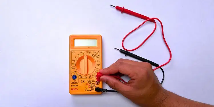
Now that you know the safety measures and precautions, it’s time to learn the basics. Without understanding all the parts of the digital multimeter and its functions, you won’t be able to operate it properly.
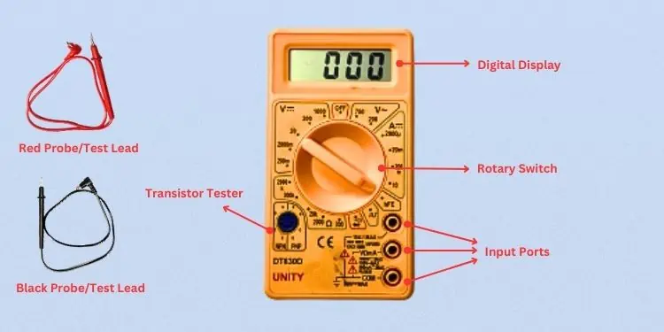
Looking at the above picture, you should already have a general idea about the instrument. Well, most digital multimeters have a digital display, rotary switch, and input jacks. However, some high-end products also come with extra buttons for additional functionalities. Let’s explore each of the parts in detail.
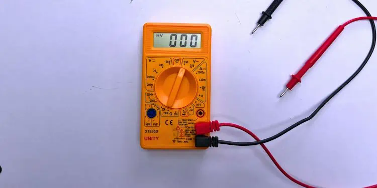
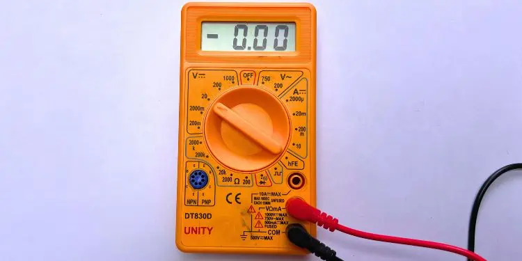
Digital Display
This is the most basic component of the instrument. Most multimeters incorporate illuminated LCD screens—some even have backlit for better viewing.
Unlike the traditional analog meters, they display in numbers which makes it easy for the users to read the measured values. It can display four values/digits and even a negative sign when the polarity is reversed (wrong positioning of the red and black leads).
Rotary Switch
It is simply the selector or dial positioned at the center that allows you toselect from the range of AC/DC voltages, currents, and resistance. All you have to do is rotate the switch in different directions.
If you’ve got a device as pictured above (a manual-ranging multimeter), you require setting the measurement values manually. However, if you have an auto-ranging meter, you do not need to hassle with the ranges as they can automatically configure them.
During the measurements, it’s essential to know the appropriate symbols. AC voltage and current have a ‘∿’notation that differentiates from the DC voltage and current, which is ‘⎓.’
Also, note that some cheap meters do not offer the measurement of AC current, like the one above in the picture.
Test Leads/Probes
Every digital multimeter comes withtwo test leads (Red and Black), also known as probes. These are simply the wires that let you connect an electrical circuit to the meter.
One end of the wire is apointed probethat is meant to touch the source device. While the pointed probe is the most popular, there are other variations—including crocodile clips, hook clips, or even tweezer probes!
The other end of the wire is usually abanana jack, which needs to be plugged into the digital multimeter’s input ports, which I shall discuss ahead.
Some older models used to offer BNC connectors, but these days, most manufacturers use the shrouded banana jacks in the meters as per the IEC’s safety guidelines.
Input Ports
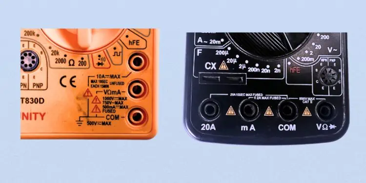
All the digital multimeters have at least three input ports—positive, negative, and a high-ampere(usually for measuring current range from 200mA to 10A). However, newer instruments also have a fourth port for the temperature, volt, resistance, and diode test.
The negative or also called the common input port is usually labeledCOM. This is where the black probe is connected and is connected to the ground of an electric circuit. No matter what you’re trying to measure, this must always be plugged in.
On the other hand, the positive or also known as the current port, is where you plug in the red probe. This is used for measuring current up to 200 mA and is mostly represented with the labelmAVΩ,VΩmA, orV/Ω/Hz.
Likewise, the third port (labeled justA, 10A⎓MAX, or20A) is used when you’re trying to measure larger currents (greater than 200mA). Here, you require connecting the red probe.
Note:Always check the maximum supported voltage, current, resistance, and also the time limitation (when measuring high amperes) next to the input ports before operating your digital multimeter.
Transistor Tester
Most digital multimeters have a transistor tester embedded into them. There are two separate fields for testing both types of transistors (NPN or PNP). When doing so, you need toconfigure the Emitter-Base-Collector appropriately, ensuring they are at the correct terminals.
Moreover, when testing transistors, it’s essential to point the rotary switch to the hFE field. In case you’re not getting the reading, you might want to reverse their position to get accurate results.
Input Buttons
If you have a newer DMM model, it’s likely equipped with multiple buttons. In some models, you get a Range button to manually set the range or simply set it to Auto.
Likewise, there are other buttons with dedicated functions, likeData Hold, Min/Max Mode, Back Light, On/Off, Frequency Counter, Relative Measurement, Shift, and many more.
Since the number of buttons differs based on the DMM type, I am not going to get detailed into them. Instead, you can look up the operator manual to know how they work and when you should use them.
How Does a Digital Multimeter Work?
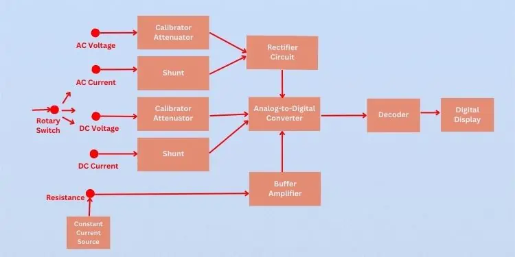
While there can be a broad range of digital multimeters, the working principle remains the same. Once you get to know how the device works, it’s not at all tedious to use it.
As per the block diagram above, to find the AC voltage of the circuit, it is required tofirst set therotary switchto an appropriate range. Next, thecalibrated attenuatorconverts the higher volts to lower volts. Then, therectifier circuit(also known as the precision AC/DC converter) converts the AC voltage into DC voltage. Finally, the generated analog values are transformed to digital by theAnalog-to-Digital Converterwhich is then displayed on the LCD screen.
Similarly, if you’re trying to measure a DC voltage, it is necessary to set the rotary switch first. Then, the higher volts are calibrated into lower volts as discussed earlier. Since this is a DC voltage, it doesn’t require a connection to the rectifier circuit and the AC/DC converter converts the DC analog signal to digital, which is now displayed on the screen.
While measuring the voltages required a calibrated attenuator, the measurement of currents requiresshunts, which basically coverts the high current to lower. Now, if you’re trying to measure an AC current, it first passes through therectifier circuit(to convert AC to DC) before the conversion to a digital signal. On the other hand, when measuring DC current, this is directly done. Once the final conversion is completed, the final value is shown on the digital screen.
To find the resistance, we should first point the rotary switch to the appropriate resistance range. Unlike the other measurements, we require aconstant current sourcehere that provides the necessary amount of amps.
Now, the digital multimeterfinds the voltage drop in the circuit,and with the help ofOhm’s law(Resistance = Voltage / Current), resistance is calculated. Finally, thebuffer amplifierwill provide the electrical impedance transformation (i.e., provide the best loading condition), and the analog signals get converted to digital before the final output on the screen.
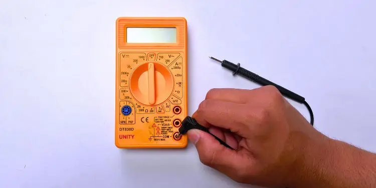
How to Use a Digital Multimeter?
As mentioned earlier, a digital multimeter helps you measure voltage, current, and resistance. Additionally, it allows you to test continuity, a transistor’s hFE, frequency, and more. Regarding the same, I will discuss the step-by-step guide on measuring each of them.
Measuring Voltage
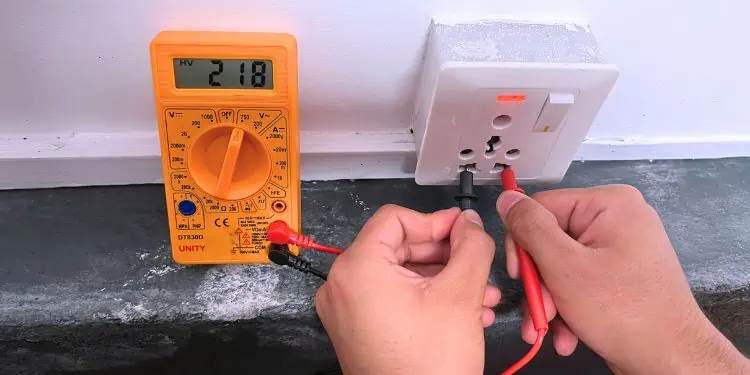
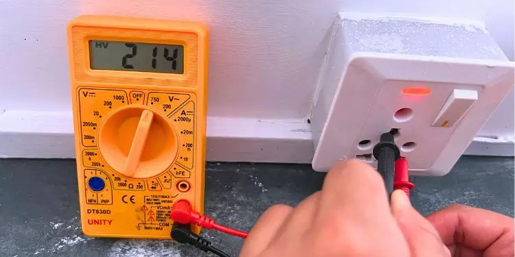
For example, to check the AC supply voltage on your house, here’s what you can do:
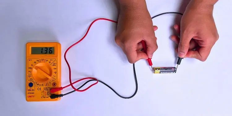
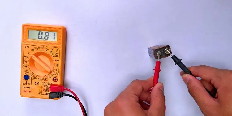
While this was for measuring the AC voltage, here’s a simple example of how to check the DC voltage of a 1.5V AA DC battery:
Measuring Resistance
For testing purposes, I am going to check the resistance of a 220Ω resistor. If you’re unaware about its value, you can compare the color code with the online chart.
Testing Continuity
In this section, I will test the continuity on a piece of wire—jumper cable. You may use any other equipment to ensure it is not damaged and is in proper working condition.
Measuring Current
For testing purposes, I first created a simple circuit comprising a 2.68V DC battery, a green LED (voltage requirement of 1.9-4V) and a jumper cable. and a matrix board to measure Direct Current (DC).
Since this is just a beginner’s guide to using a multimeter, I have not included the necessary steps for measuring Alternating Current (AC).It can be a risky process and can prove to be fatal.If you’re already an expert, you can use a similar procedure with extreme precautions or use a clamp meter.
hFE Test for Transistors
Hybrid parameter Forward current gain, common Emitter (hFE) determines a transistor’s current gain or amplification factor. Every transistor has its own hFE value, and it ranges from 10 to 500. To test yours, follow this quick steps:
Computing Square Wave Output, Frequency, and Temperature
Along with voltage, current, resistance, continuity, and hFE, it’s also possible to compute the square wave output using any digital multimeter. To test this, you may use anoscilloscope or build one using Arduino. Then, use its software to measure the frequency.
Unlike the low-end DMMs, some high-end instruments let you measure the frequency directly as they have a separate Hz field.
Likewise, some also allow measuring temperature. You can check your manual to learn more about them.
