It has been the dream of our editor-in-chief, Avram Piltch, to walk around an event with the latest Tom’s Hardware headlines appearing on his conference badge. Today we make that dream come true. The Raspberry Pi Pico W is a surprisingly capable device for under $10. We’re going to use it with a few Pimoroni products, chiefly the Pico Inky Pack, a 2.9-inch, 296 x 128 pixels epaper display. We’ll also have a LiPo battery and a LiPo Amigo Pro charge controller to top up the battery and keep the news flowing. But how do we house all of this awesome?
It works and I have a power solution from @pimoroni #LivMF24 pic.twitter.com/n2FrZtciDCJune 27, 2024
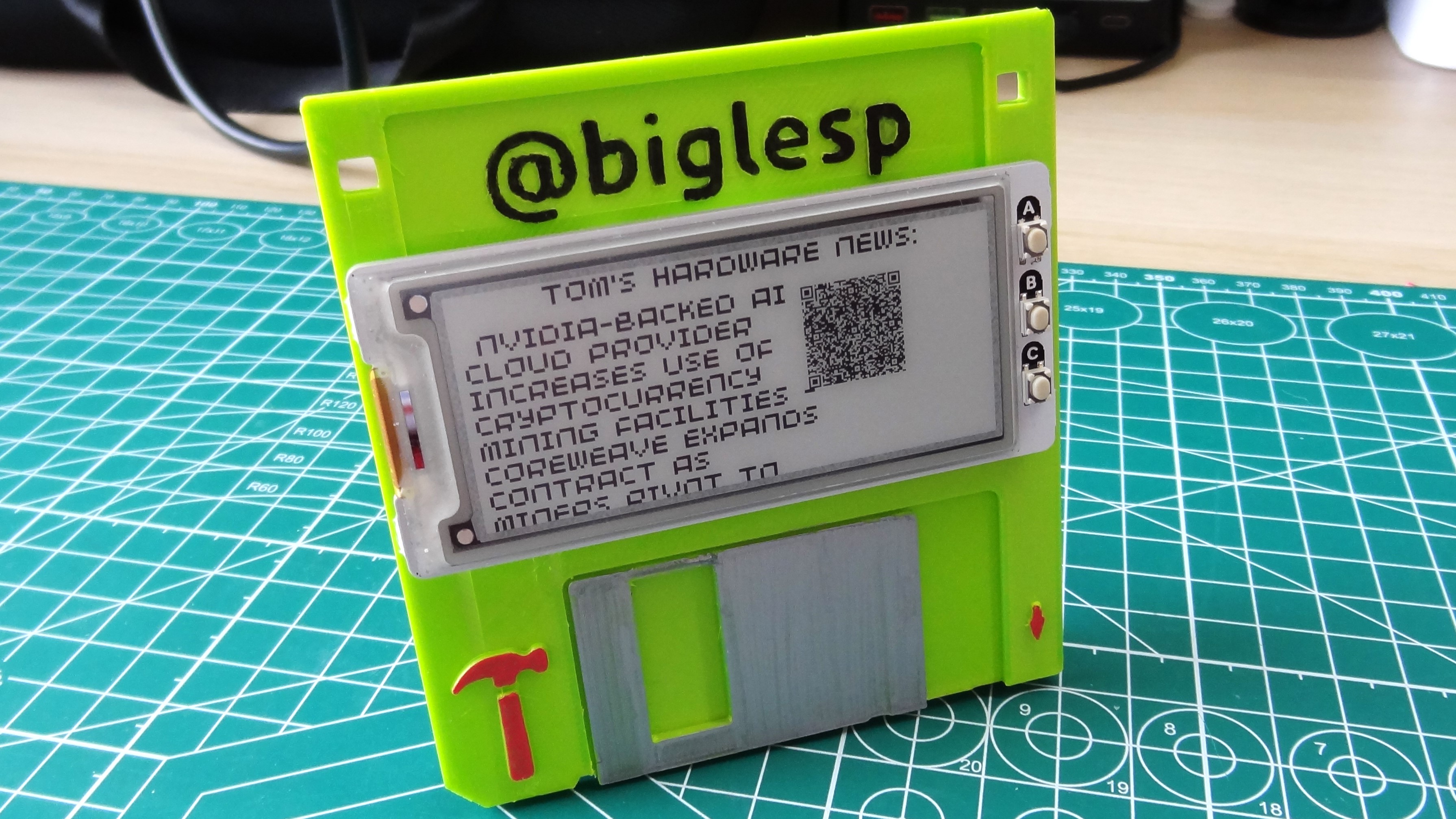
Obviously we 3D print something. This project came about by pure chance. I had to clear out my desk to find something, and I placed the Pico Inky Pack on top of a floppy disk, and that got me thinking about whether I could use the floppy disk as a holder. It looked cool, and it would be a talking point at conferences. The added bonus of live news appearing, and also being accessible via a QR code, was a massive boon.
The code for this project is heavily modified from aPimoroni exampleused for theInky Frame 7.3. I simply removed some sections and added an extra bit to parse unknown characters. Many thanks to Pimoroni and Gadgetoid for the code.
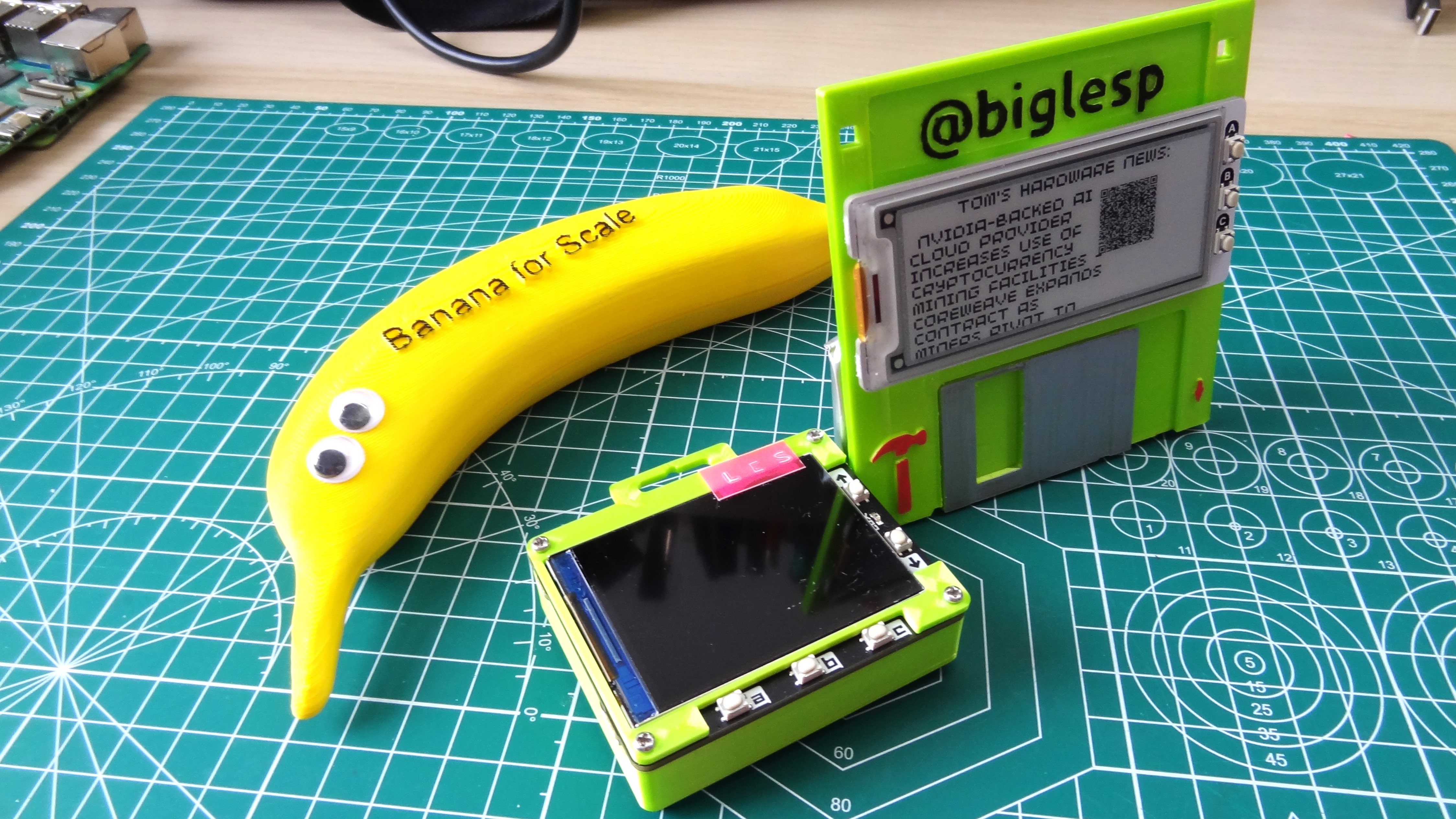
I seem to have a thing about making conference badges.Two years agoI made a Tufty 2040 powered LCD conference badge forLiverpool Makefest. I used the same Overture green silk PLA filament too! But for 2024, I wanted to make something a little more useful, a live Tom’s Hardware news headline on a badge at a maker event is a great idea!
Enough talking; we have plenty of work to do. I’ve broken it down into stages. The 3D print stage can run while we write the code. Then we can assemble the project ready for our next event.
For this project you will need
- Check out our list ofBest 3D Printersfor recommendations if you don’t already have one.
The 3D printed disk
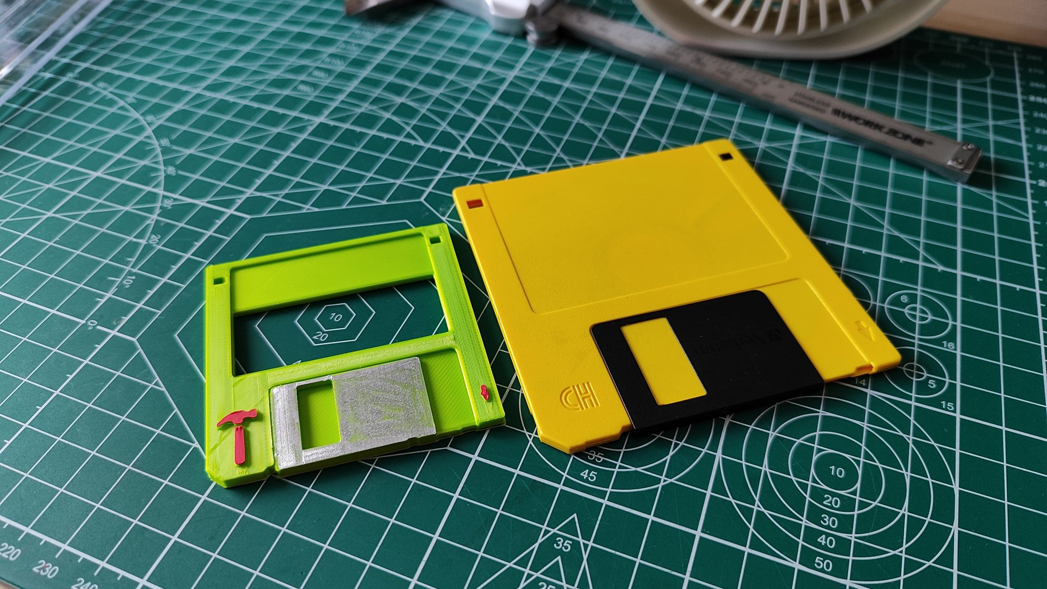
Described by a friend of mine as “a 3D printed save icon” (I feel old!) The novelty case that holds the project together is a 3D printed, 3.5-inch floppy disk. Specifically this is a floppy disk created byMattia Vannucci, and is available via Printables.
Get Tom’s Hardware’s best news and in-depth reviews, straight to your inbox.
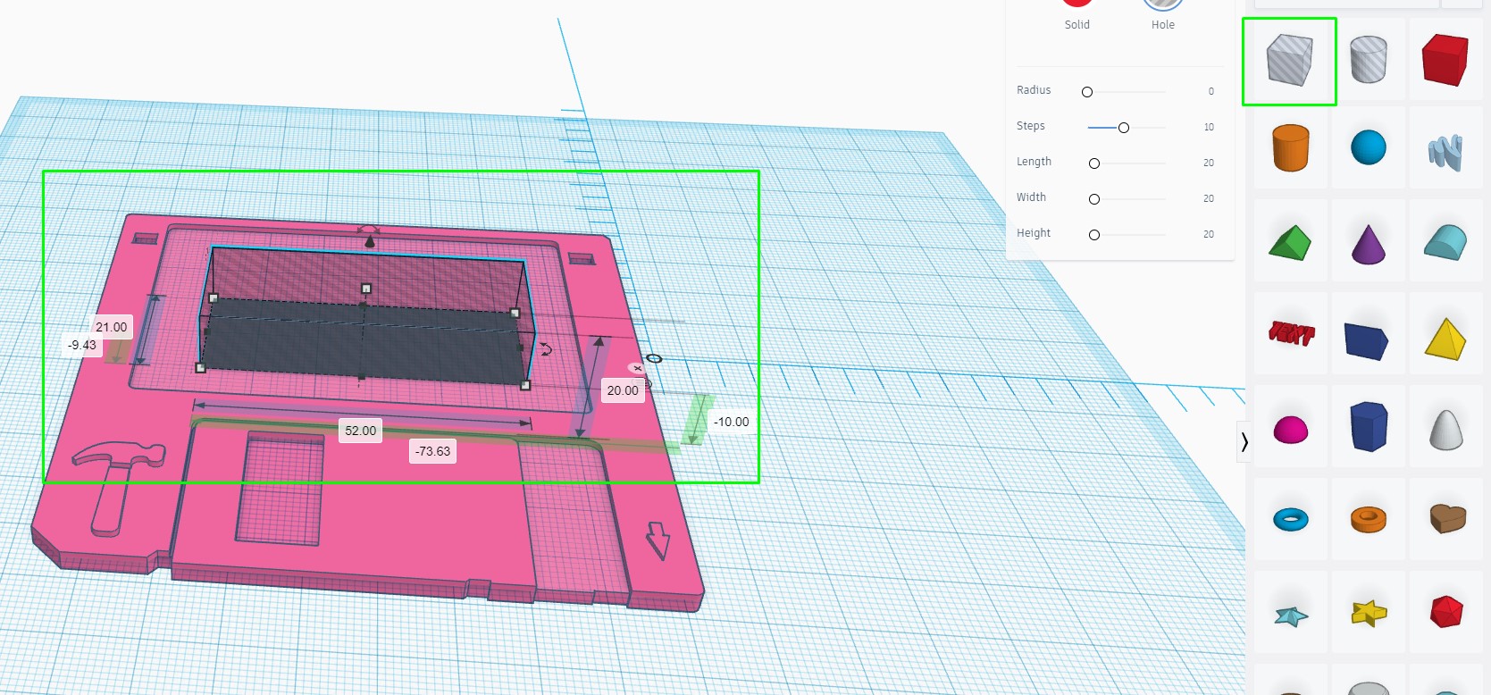
I downloaded the simple floppy STL file and edited it in Tinkercad. Ensure that the size of the disk matches the dimensions of a 3.5 inch disk (88.8 x 91.77 x 3.3mm). We forgot to do this and ended up with a very small floppy disk.
1.Using the Box void tool, create a void that measures 52 x 21 x 20mm and place it in the center of the disk.The length of the 20 pin GPIO headers of a Raspberry Pi Pico is 51.38mm, and the two rows are spaced 20.38mm apart. I added an extra 0.5mm for tolerances.
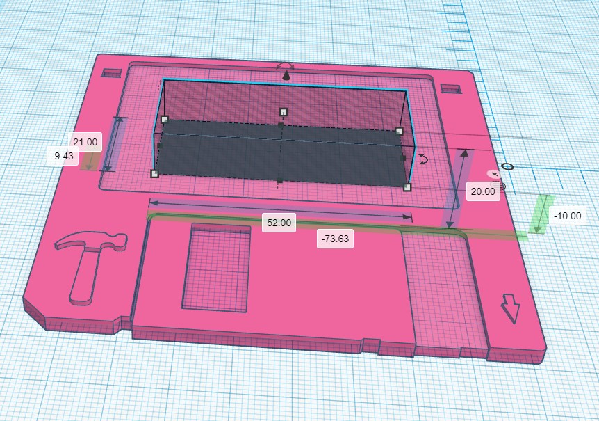
2.Drop the void so that it cuts through the disk.Around 10mm drop is plenty.
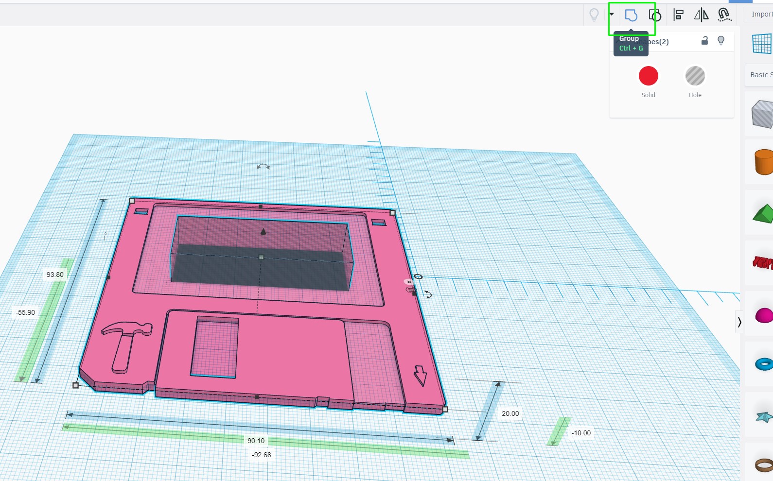
3.Select both the void and disk and click on the Group icon to merge the two objects.This will create a void inside the disk, large enough for the GPIO pins of the Pico and the Pico Inky to attach.
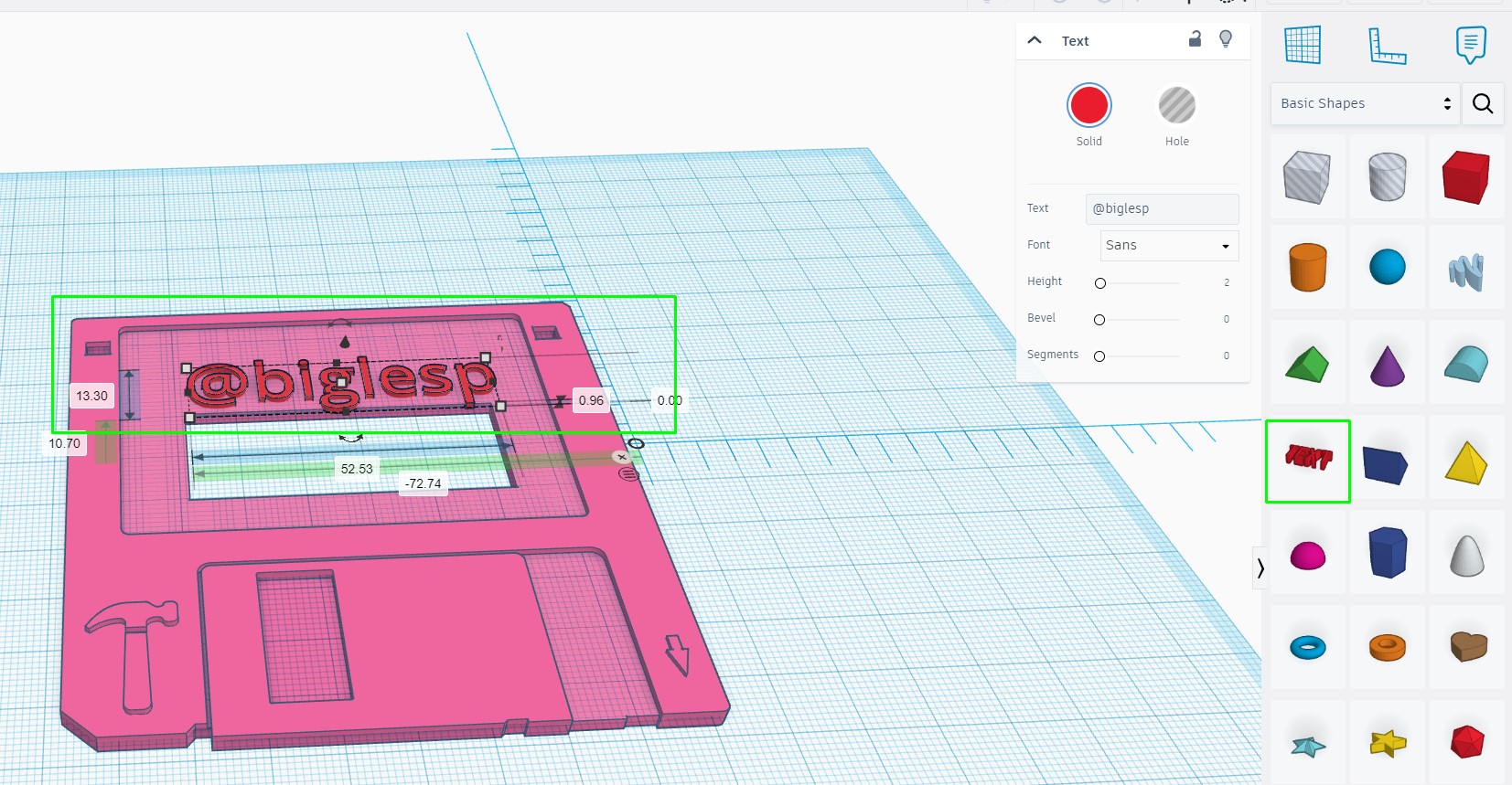
4.Using the text tool, add your X/Twitter handle to the label area of the badge.This is optional, but it helps people identify you at an event. There is a limited selection of fonts offered via Tinkercad. This step can also be reproduced in the latest version of PrusaSlicer, which can access all of the fonts on your system. We chose to use the PrusaSlicer method.
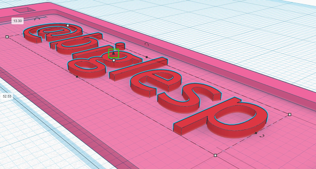
5.Using the “cone”, visible when selecting the text, ensure that the text is embedded into the diskandthen use the Group icon to merge the two objects into one.
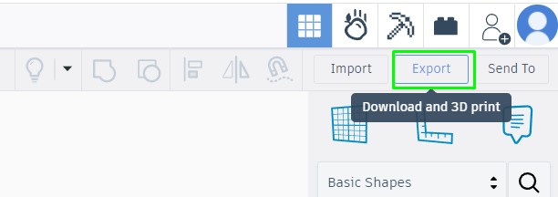
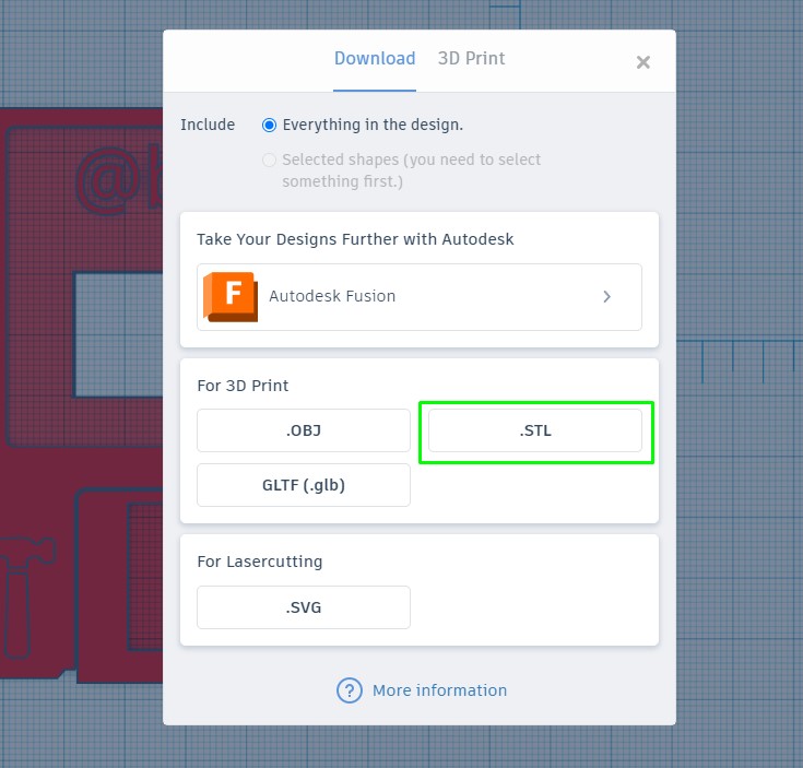
7.Click on STL to download the file to your computer.
8.Open your 3D printing slicer software, import the STL file and save the file as GCODE to a removable device or send directly to your printer if it has the facility.This step depends on your preferred slicing software and choice of 3D printer. I am using PrusaSlicer with anElegoo Neptune 3 Pro. I have to save the file as GCODE to a micro SD card, insert the card into the Neptune 3 Pro, and start the print manually.
9.Print the disk.It should take between 90 minutes and three hours depending on your 3D printer. My print took 3 hours, because I set the layer height to 0.20mm and infill to 20%. I also enabled ironing of the top layer. I wanted a smooth layer to replicate the injection molding used in real floppy disks.
Coding the project
Right now we have a plastic disk being printed, let’s turn our attention to writing the code that will make this project. We’ll be using Pimoroni’s version of MicroPython, as it comes with all of the modules (pre-written Python code) that enable us to access the Internet, download the news and display it on the e-ink display.
1.Download the Pimoroni MicroPythonUF2 file for Inky Framefrom theGithub repository.
2.Push and hold the BOOTSEL buttonon the Pico, then connect to your computer using a micro USB cable. Release BOOTSEL once the drive RPI-RP2 appears on your computer.
3.Drag and drop the UF2 fileonto the RPI-RP2 drive. The Raspberry Pi Pico will reboot and will now run MicroPython.
Pirate Python is the name for Pimoroni’s version of MicroPython for the Raspberry Pi Pico. If you have never used MicroPython, it is a version of Python 3 developed for microcontrollers. If you can write Python, then you can write MicroPython. To write MicroPython code, we need to use a dedicated editor and the default, basic editor is Thonny which is what we shall use for this tutorial.
1.Download and install Thonnyfor your OS, if you don’t already have it. You can grab it for free from theThonny website.
2.Connect the Raspberry Pi Picoto your computer and inThonny go to Tools > Optionsandclick on the Interpreter tab. From the interpreter, dropdown list select MicroPython (Raspberry Pi Pico). The port dropdown menu can be left to automatically detect the Pico.Click Okto close.
3.Check that at the bottom of the Thonny editor, that you may see the Python shell and that it is running the Inky Frame MicroPython.
4.Create a new file and save it to the Raspberry Pi Pico W as secrets.py. Inside the secrets file add your Wi-Fi access point name and password.For portability, I would recommend using your phone as a hotspot.
5.In the editor, create a new file called main.py and save the file to the Raspberry Pi Pico.Saving the code as main.py will force the Pico to load the code when it is powered on.
6.Import a series of modules.We need to import a bunch of modules that enable our project to go online and download the news, then display it on the e-ink display. PicoGrpahics is used to write to the e-ink display, and we tell the module that we are using the Inky Pico pack. Network and secrets will get our Pico online.Uasyncio is an asynchronous task manager that will run the code. Urllib and urequest are used to make HTTP requests that retrieve the raw data. Gc is a garbage collector, as we will be generating a lot of data. QR code creation is possible via qrcode, and lastly time is used to control the pause between updates.
7.Setup the Wi-Fi connection by first turning it on, then connecting to your Wi-Fi access point.
8.Add a five second pause, then check that the connection is successful.You don’t need to add a pause, but in our tests, not having a pause introduced a high chance of connection failures. Waiting five seconds seemed to drastically reduce the chance of this happening.
9.Create an object, URL to store the RSS feed that you wish to use.
10.Create an object, UPDATE_INTERVAL to store the delay between refreshes. Change the number after the multiplication sign to your desired delay time in minutes.We set it to five minutes, but a longer delay will increase battery life.
11.Create an object, graphics, to more easily work with the PicoGraphics module.
12.Using the graphics object, get the width and height of the screen (in pixels.)
13.Set the font to bitmap6.We can useother fontsbut be warned, you will need to alter the position of text to accommodate the font change. Bitmap fonts can be scaled using integers (1,2 etc) while vector fonts can be scaled using floating point numbers.
14.Create a function, read_until, to read the stream of data retrieved from the RSS feed.
15.Create a function called discard_until.We’ll use this later.
16.Create a function to parse the XML stream.This function will look for specific tags and break down the data into something that MicroPython can understand. This function is huge, and we’ve recreated it in its entirety for clarity.
17.Create a function, measure_qr_code which will measure the available space for a QR code.
18.Create a function, draw_qr_code which will be called later in the code to create a QR code for the headline displayed on the badge.
19.Create a function, get_rss to retrieve the RSS feed data, store it in an object, stream, and then parse the data to retrieve the headline (title) and the URL (link). A try / except is used to handle any errors.
- Out of the functions,create a while True loop to run the main body of code.
21.Call the get_rss function and store the output to an object called feed.
22.Set the pen color to white (15), clear the screen and then set the pen color to black (0).
23.Write the title to the top center of the display.The syntax of this line is pretty simple, once you understand the sequence. First we have the string, then the x and y position (in pixels) where the text will start. Next is word wrap, set to 300 so that our text does not wrap. Finally we have the font size, scale. Using 2 is good for legibility.
24.Create an if conditional test to check that we have a valid feed.If the feed is valid, the code within the if condition will run.
25.Create an object, headline, to store the title (headline) of the first entry from the RSS feed.
26.Using another conditional test, check for en dashes in the title.The Bitmap character set has no means to display an en dash, so we need to replace it with a hyphen instead. This test can be omitted if you are using a source that doesn’t have en dashes in its headlines.
27.Print a message to the user, alerting them to an en dash, then update the headline object to replace en dash with a hyphen.
28.Create the else condition to continue the code.If there are no en dashes in the headline, then the else condition will activate and pass the code to continue onwards.
29.With the pen set to black, write the headline to e-ink display, and then create the QR code at a specific location on the screen.
- For error handling, create an else condition that will display an error message on the e-ink display.
31.Update the screen to show the headline and QR code, then pause the code using the UPDATE_INTERVAL object.
32.Save the code as main.py to the Raspberry Pi Pico W, then click on the green Run button.
After a few seconds, the screen will update and show the latest news headlines from Tom’s Hardware (or from whatever RSS feed you have chosen to use).
Complete Code Listing
We’ve placed all of this code and high resolution images in aGitHub repositoryfor easy access.
Some assembly required
The 3D print is hot off the print bed, and we have a working project. Now we just need to build it and then power it.
Assembly is simple. Place the Pico Inky on the front of the disk, and making sure that the board is orientated correctly, push the Raspberry Pi Pico W GPIO pins into the header of the Pick Inky. If you’ve not soldered the GPIO pins onto your Raspberry Pi Pico W,we’ve got a guideto help you do that.
Using a little double-sided foam tape, secure the Pico Inky to the disk. This may take a little trial and error.
Our power supply is a 2000 mAh LiPo battery. We would advise you to purchase a battery in a protective case, such asPimoroni’s Galleon. LiPo batteries can be dangerous when damaged, and a hard shell case is a must for a wearable.
We could wire the battery directly to the Raspberry Pi Pico W, but then we would have no power switch, or means to recharge the battery. Instead we chose another Pimoroni product,LiPo Amigo Pro. This board receives power from a USB C connection, and can power the project directly, while charging the LiPo battery.
Using a JST connector, snip the end off one, strip and tin the wires using one of thebest soldering irons or soldering stations(I used theFnirsi HS-01, a great and cheap soldering iron.)
Check that the red wire of the uncut JST connection goes to Device + on the Lipo Amigo Pro. Black should go to Device -.
Solder the positive wire (typically red) to the VSYS pin of the Raspberry Pi Pico W. Solder the GND wire (black) to the GND pin next to VSYS. Please refer to thisPico pinoutbefore soldering. Check for any shorted connections before connecting the battery. VSYS and GND wires shouldnotbe touching.
Connect the battery to the BAT connector and after a final wiring check, press the PWR button on LiPo Amigo Pro to power up the Raspberry Pi Pico W. Because we saved the code as main.py, the Pico W will run the code when powered up.
Check everything works before moving on. Using some more double-sided foam tape, secure the LiPo Amigo Pro and battery to the back of the disk.
You’ve just made your own walking news ticker for maker events.
Les Pounder is an associate editor at Tom’s Hardware. He is a creative technologist and for seven years has created projects to educate and inspire minds both young and old. He has worked with the Raspberry Pi Foundation to write and deliver their teacher training program “Picademy”.
